Monday, October 27, 2008

Hello All,

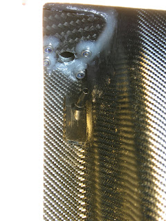
I had a recent comment on the blog for an update. Its not that I have been forgetting to update the blog, but actually I have not made much progress lately since I have been doing some other things. I am basically at the stage where I need to glue the stuffing tubes in place. Here are some pictures of the jig I have made to make sure that the motors are nicely aligned with the stuffing tubes when I glue them in place. The also is sets the distance of the ends of the stuffing tubes from the motor based on my hubs. There will be about a 4-5mm gap between the stuffing tube and hub; from my understanding it should NOT be any more than this.


At the transom the stuffing tubes extend about 5mm into the Arneson drives, I don't see how it could be more.

Wednesday, September 24, 2008

Slooooooow

Sorry, progress is going a little slow these days as I have been side tracked on some other projects. I have however made a little progress by gluing both the motor bulkheads in place.

In order to get the alignment correct I made a small template I could attach to the bulkhead as if it was the motor through which I could pass the stuffing tube so that I could get the bulkhead aligned correctly.

The pictures tell the story I hope.


The bulkhead was glued on one side (side facing bow) with an epoxy resin mix and cotton flakes. When this was dry I removed the shaft and template and laminated the backside of the bulkhead with resin and a CF cloth in strips of about 1cm wide.


I then repeated the process for the second bulkhead.

Saturday, September 13, 2008

Motors are here

My Lehner 1940/8's finally arrived so now I can continue the build. Motors are fresh from the factory dated 08/2008 :-)


So the first thing I wanted to do was get a feel for the layout of the batteries and motor with regards to the optimal CG of the boat which according the Hanspeter is 31.5cm from the transom of the sponson. Trying to keep my Lipo's as close to the CG point as possible (if the motors are too far back then you need to move the batteries forward and away from the CG point) puts the bulkhead for the motors at around 9.8cm from the rear flange of the top cover opening.

Note: my bulkheads are the ones Hanspeter sells

Next I prepared the stuffing tubes to give them a bit of an angle so they would mate nicely with the motors's axel and the hole in the sponson for the drives; of course the less angle the less fricition. To give you an idea of the angle I am using you can look at the following picture. DON'T make more than ONE bend. For a brass tube you can bend by hand gently, make sure to have the tefflon liner inserted in the tube.

My stuffing tubes are made from standard 8mm brass tubing into which I will insert some teflon tubing followed by the flexi-cable.


I imagine there are several ways of going about this and placing the angle in a different spot (maybe using two bends instead of one... NOT!!) or making the bend more progressive but this is what I came up with. Please comment of you have a better method or suggestion. The propeller shaft side of the stuffing tube can stick out about 1cm from the transom of you are using the HPR Arneson drives.

The bend in the stuffing tube is at an exact angle so that it meets squarely with the axel of the motor and are exactly inline with the propeller shafts at the transom (this is important), a bit of trial and error is needed here and of course also depend on the distance of the motor bulkhead from the transom.

The final result loosley fitted looks something like this.


If you cut the stuffing tube before hand leave enough length so that it sticks through the motor mount as we will use this for alignment in the gluing phase later on.

Once you have everything fitting nicely for both starboard and port motors you can glue the mounts into the hull.

I will cover this process off tomorrow.

Wednesday, September 3, 2008

Work of art

While I am waiting for my motors for my HPR 115, which I have heard are now on their way from Germany, I decided to side track a little and build my Duzi Nova R5 helicopter.

What a work of art, just like the HPR 115!!

I let you check out the pictures, need I say more.


Monday, September 1, 2008

Nothing much to report

Nothing much to report at the moment...

I am still waiting for my Lehner motors to arrive and feel that there is not much I can do with the hull in the mean time. I basically want to get the centre of gravity figured out before I glue anything else in the hull. Mainly the front bulkhead, engine mounts and battery support plates.

I did cut out of a 2mm carbon sheet the two battery plates. Its recommended by Hanspeter to not mount the batteries directly against the bottom of the sponsons.
Mine measure 6.7cm wide by 24.5cm long which gives me enough room to move the batteries forward and back to change the point of CG.

Once I have decided on the correct mounting position of these plates I will need to cut a little wedge in the outer side of each plate to get it to sit flat since there is a little hump where the first step on the bottom of the hull is.

I have also observed several different styles of mounting the batteries to the mounting plates, not sure what I am going to do here yet.....


Lastly I have been giving the paint job a thought and have some ideas, stay tuned

Tuesday, August 26, 2008

Assembling the propeller shafts and flexicable

While I am waiting for my motors to arrive I went ahead and assembled the flexicable (Left + Right) to the propeller shafts. You need 4.75mm flexicable, one clockwise rotating and one counterclockwise rotating.

I sanded the flexicable by putting one end in the drill and turning at a medium speed while sanding about 1.5-2cm of the other end of the flexicable. IMPORTANT make sure to turn the drill in the correct rotational direction with regards to the flexicable so you don't unravel it.
If you did not realise by now the flexicable has a specific direction of rotation and since we have twin shafts and they are counter rotating we have a left and right. So depending on which one your are spinning in the drill you will need to change directions for the other one.

I also sanded the inside of the propeller shafts using some sandpaper rolled up on a stick so it just fits inside the shafts.

I glued the cable into the shafts using Loctite 648 which is a high strength, high temperature product specifically designed to assemble cylindrical pieces. The 648 specifically allows for a little more "space" between the two parts being assembled.


Before gluing do a pre-fit check to make sure the flexicable fits all the way into the shaft, if it does not you might need to sand a little more then clean both the inside of the shafts and the flexicable extremely well, I used acetone and a toothbrush.

Allow 72 hours for this to dry and you should not have any problems with the shaft parting from the flexicable.

Saturday, August 23, 2008

Downtime..

Well, I have been busy with a few other neat things and I am waiting for my Lehner motors to arrive so I can continue, of course there is still plenty to do but one of the bigger items is the engine installation.

Back soon ....

Wednesday, August 20, 2008

Moving on

Well after letting the resin dry for the water intakes I was able to do some rough finishing and sand them flush with the bottom of the sponsons. Here is a shot before sanding.


And this is what it looks like after some sanding. I still need to decide if I take Hanspeters approach and cut the nipplesof these plastic intakes, drill the 5mm hole all the way through and insert a 5mm tube. But I don't need to make that decision just yet.


The next task was installing the hydraulic look-a-like steering rods for the rudder. This took a while to get everything aligned properly but is straighforward except getting the nuts on the bolts! Small hands or good tools help!

I measured 4.5mm vertically from the deck and 9mm horizontally from the standoffs. To get to these measurements I put some double sided tape on the mounting bracket and then experimented till I found the position I felt was just right. Basically I put a straight edge up against the underside of the rudder arms and marked where it met the hull which gave me the vertical position. For the horizontal position I just kept hydraulic cylinders parallel with the standoff.


I drilled the 2mm holes by hand (like most of the other smaller holes) to make sure they were perfectly lined up.


The hole for the steering cable was a bit of a dilema, either you make a small hole the diameter of the plastic/teflon sleeve at just the right angle and in just the right spot or you make a bigger hole like the one in the middle of the mounting plate. I chose the latter and made a good size hole (4mm). When I make the final installation of the steering arms I will surround the plastic sleeve with silicone.


The other side went a lot quicker once I knew the measurements and had built up a little self confidence :-)


Done!

Tuesday, August 19, 2008

Prefect Fit!

First of all, I received my YGE ESC's today and these are the biggest (and most expensive) I have owned to date. Not convined on how effective the water cooling system is, I would have thought a metal plate on the fets with cooling water circulating around it would be the way to go. Here the brass tubes (one on each side) just seem to be soldered to the PCB and water simply runs through the tubes. Does the PCB conduct heat that well?
They are supposed to be good so we will see.


I installed the water intakes today which was about a 2 hour job. I did end up moving the cutouts for the intakes 2mm further away from the tunnel which makes the total distance of cut closest to the tunnel 5mm, thank goodness I did because they would never have fit otherwise. I still had to re-shape the intakes quite a bit to get them to fit properly, they are basically right up against the sides of the sponsons.


I sanded the surfaces, cleaned everything with acetone and glued them in the hull with the resin + cotton flake mix. They will stick out a little on the bottom of the hull but thats fine and will make it easy to get a nice flush finish.


The suggestion from Hanspeter is to cut the nipples off the intakes and drill the 5mm hole all the way through the intakes, then push a short piece of 5mm stainless (thin walled) tubing up through the intakes and attach the silicone tubes. He recommend not to glue them in but just seal with a little silicone, that way its possible to replace them for whatever reason.

More of a tight fit

This evening I drilled the mounting holes for the shaft support plates of the arneson drives. This was fairly straight forward however the rear mounting holes are so close to the the aft of the hull that the nuts for the two rear most bolts don't sit flat so I need to come up with a solution here.


I also started tapeing off the cutout for the water intakes based on a distance of 30mm from the transom of the sponson and 7mm from the inside of the sponson. (picture borrowed from www.rc-silverboats.de)


But I am not mounting the same kind of system so I am probably going to move it a little further from the inside of the sponson by maybe 2mm. The picture below is what it looks like without the additional 2mm adjustment.


I will save this task for tomorrow.

Monday, August 18, 2008

Good news

Good news, the resin holds the 3mm stainless nylon locknuts for the arneson drive mounting screws prefectly and I was also able to unscrew all 8 without too much problem ... pheuw I can take a deep breath cause I really was a little worried with this step.

Important!! DO absolutely put grease on all of the 3mm drive mounting screws and the back of the drive plates. It seems that the resin does find its way around.

Regarding the screws, M3 x 10mm seems to the the right length for the arneson drive mounting plates if you have reinforced the transoms of the sponsons.
M3 x 10 also works well for the drive shaft support plates.

Sunday, August 17, 2008

Tight fit!

This evening I drilled the 3mm holes in the back of the sponson for the arneson drivers as well as the two 8mm holes for the stuffing tubes.

Regarding the position of these you can refer to my earlier post regarding the vertical alignment.

For the horizontal alignment basically the drive shafts need to be perfectly parallel to the inner walls of the sponsons and you want to keep everything as close to tunnel as possible. You can measure this with a straight edge and a ruler or an inclinometer. I did both but decided the ruler method was just as accurate.


Guide helps to centre hole


Its a serious tight fit trying to get the nuts on the lower (thise nearest the bottom of the sponson) screws of the arneson drive, I actually had to grind away a little with the dremel on the inside of the sponsons to make enough room for the nuts which did not make me too happy. Maybe thats one of the reason's Hanspeter recommends the 1mm space between the bottom of the transom and arneson drive mounting plates (see my previous post). Mine are actually spaced at 0.5mm

I also decided on going for the option of glueing the stainless M3 lock nuts to the inside of the sponson transoms for the arneson drivers. I am not sure this is the right thing to do but I will find out in 24h when I try and unscrew the drives.

I hope that:

a. the screws are not glued
b. that the resin is strong enough to retain the nuts


Its important to sand all the sides of the 3mm stainless lock nuts and then clean with some acetone so that the resin adheres properly.

Saturday, August 16, 2008

The Rudder

A bit about the rudder installation

The rudder attaches with screws from the inside of the standoff and since the screws don't sit on a flat surface some additional work needs to be done.

Of course there are several ways of doing this but here is roughly how Hanspeter explained the rudder installation. Cut four 30mm long pieces of 4mm (inner diameter of 3mm) stainless steel or brass tubing, roughen up the outside with some sand paper and clean with acetone. You will also need some epoxy resin and four 3M x 35mm long stainless steel hex screws.

Rudder tubes and screws


Action

Drill 4mm the holes for the rudder and get everything ready for rudder installation. Since the screws mount from the inside of the standoff to the rudder which has 3mm threads it can be a little tricky to get aligned perfectly. A jig can make things a lot easier :-)


Once you have drilled the four 4mm holes in the rudder standoff proceede as follows.

Push the four tubes into the drilled holes so they are flush with the back of the standoff, optionaly put a little grease on the back of the standoff so the expoy won't stick to it in case some epoxy manages to squeeze through somewhere and then screw the rudder onto the hull.

Push the tubes in flush with the standoff

Screw rudder on


Once this is done and everything looks ok you can "pour" some epoxy resin (I thickened mine a little with cotton flakes) into the back of the standoff being carefull not to cover the screw heads with epoxy, I used a syringe with a large diameter needle! You should only be "glueing" the tubes. For safety you can also apply some grease to the screw threads and heads to avoid epoxy sticking to them.

Before and after resin pour


Then put the hull aside somewhere safe with the bow pointing up into the air and let the resin set. Make sure the boat is perfectly vertical in both axis.


And now time for bed.....

Oh and I almost forgot, I also glued in two 2mm thick CF plates (starboard and port) to strenghen the back of the sponson where the arneson drives get mounted. This is not absolutely required but when I talked about it with HP he said it was probably a good thing. Hp does not sell these so you need to make your own. I have also read that there is someone else selling these as part of a CF kit for the HPR 06.


Friday, August 15, 2008

Small screws big $$

So,

You want some nice screws for the windshield of the HPR.. Ouch!

I just found some M1.4x8 in stainless steel with a hex head (sadly not button head) but the price is pretty steep... around 50$ for 30 screws, thats a lot of candy!

Just a thought but Silver paint might do better.

A comparison with the M3x35mm screw used for mounting the rudder


While I am on the subject you have a choice here. Mount the plexi windshield provided by Hp or just paint one on. I am going the paint route because I don't want to make a big whole in the top with the risk of water gushing in on a blowover. There have been stories of blowovers and crushing windscreens.


If you go the plexi windscreen route its highly recommended you layup some glassfibre on the inside to keep the windshield firmly in place!!

Hmmm what distance to mount arneson drive plates from trailing edge of sponson...

There was a question asked by me in my thread about the build over in Rum Runner forum about where exactly the arneson drive plates should be mounted on the backboard of the sponson's.
How far above the trailing edge of the last step should it be?

I reasoned that it should be 2mm above so as not to disrupt the water as it leaves the trailing edge. But I have been told by others that it should be flush with the bottom of the sponson based on Achim's setup which did a stunning unofficial 184Kmh but I feel that a lot of that had to do with the power plants and not the tuning. The real test would be to have two identical setups in terms of Motors, ESC's, Props and batteries.

Meantime Hanspeter has gotton back to me recommending a distance of 1mm between the bottom of the sponson and the botton of the drive mounting plate and this is what I will do.

Pictures to follow.

More parts...

Great

I just got confirmation for my power system order which should be here next week.

2 x Lehners 1940/8 + Water jackets
2 x YGE Navy 155 ESC's

I opted for the Navy 155 over the Navy 120 because the 120 takes max 6s and if ever I want to go crazy and try some 7s in the boat I won't be able to with the 120's. 155 go up to 8s

YGE also proposes an "upgrade" capacitor kit which is recommended when wire lengths are longer than 20cm or when using max voltage but I don't think I need these at the moment.

Wednesday, August 13, 2008

Ordering stuff needed for the build

Well I have a lot of stuff I need to order before I can really get kicking!

Here is a short list of what I am missing.
  • Metric stainless steel hex headed screws, I ordered an assortment of m2, m3 and m4 + lock nuts from (microfasteners)
  • Epoxy resin (LF 285 with 90min hardener) (http://www.swiss-composite.ch)
  • 1 meter of CF ribbon, 10mm wide (http://www.swiss-composite.ch)
  • Cotton flakes to mix with the resin when "glueing" engine mounts and servo mount etc.. (microballons should do as well) (http://www.swiss-composite.ch)
  • Some small paint brushes and mixing sticks
  • Black sikaflex marine silicone
  • Loctite 648 for glueing the flexicable to the outdrive shafts
  • 2 mm CF plate for making the backboard re-enforcement where the arneson drives mount
  • 4mm and 5mm stainless steel tubing with thin walls
  • 8mm brass tubing and 7mm teflon tubing for the flexicable stuff tubes.
  • 4.75mm flexicable
  • Motors + watercooling jackets, ESC's, 6mm connectors and motor hubs
  • Water cooling intakes which will be modified with stainless tubes

Saturday, August 9, 2008

The HPR 06 Offshore Class 1 cat by Hanspeter Rotschi

I just got back from a visit to Hanspeter Rotschi (http://www.swissmodelpowerboatteam.ch) and WoW, what a super nice guy and what a super nice hull!! Its got Swiss Quality written all over it :-)

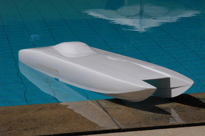
If you are looking for the best 1 meter size offshore cat hull money can buy then this has got to be it, the HPR 06. Its an exact replica of its true life Offshore Class 1 big brother down to every detail including the smallest ones related to the tunnel, sponsons and deck which give this boat handling abilities that no other RC cat in this size class can match (just my opinion).

You can have the boat in three flavors, standard fibre glass, carbon fibre and carbon kevlar; the carbon fibre hull being the most expensive due to raw material costs. All of them are 3 layer with 2 layers of glass fibre and the third layer being glass, carbon or carbon kevlar depending on the version.
I realise that people in the US might feel the cost of this hull is a little high but belive me this is mainly due to high raw material costs and the weak dollar. I have seen hp's invoices for raw material's and I promise you that he is not making a huge profit on these boats and the workmanship is par non!
I bought the Carbon fibre boat which is basically made to order, he does not stock this one so my hull literally came out of the mold the day before I arrived to pick it up :-)

It does not stop there, HP also sells all the important hull related hardware you need to build the boat and every piece fits perfectly which makes for a super nice, no fuss, build.... I think.
Since I have not built one yet I have yet to prove that last point to myself.

I intend to document the build here and help out Hanspeter who's english is not that great by transfering the knowledge he gave me by blogging about the build. I am also trying to target those who do not have much boat building experience (including myself) so bare with me all you guru's.

This will hopefully unload his inbox a little and give him more time to build boats (which is what he does best) and especially to finish his HPR 08 "Mystic" for which he is already back ordered several boats and is slated for production around Sept. 2008 he says. Its the same hull design as the HPR 06 but its 1m85 long and is not a 100% scaled down version of the real things since a few changes have been made primarily to enable the installation of twin Zenoah's in a perfectly vertical manner.

There is also a short HPR 06 build documented in German here http://www.rc-silverboats.de/Baubericht/HPR115.html for those of you who speak German.

NOTE: Some of you might notice the boat stand in some of my pictures, there was a very limited run of these done by a friend of Hanspeters and they exist no longer. Hanspeter does not sell or have any of these anymore. However if someone is interested I would be happy to trace the profile of both sides of mine and then I am sure it would be fairly trivial to make your own out of wood or whatever.

So to kick things off here are a few pictures of what I walked away with from Hanspeter's "shop"

The Hardware currently sold by Hanspeter for the HPR 06, ain't it beautiful! These engine mounts are for Lehner motors.


And now a few pics of the hull as delivered